Published August 3, 2026 | By HDPTH Technical Editorial Team
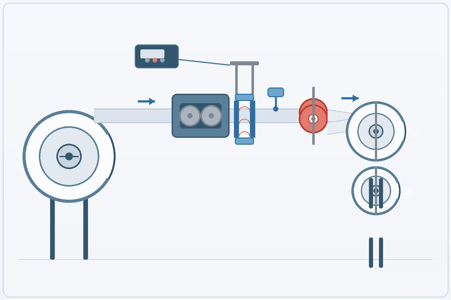
Specifying a slitter rewinder involves many technical decisions that affect long-term production efficiency, and one of the most consequential is the web guide sensor. Assuming that a standard, default web guiding system will handle any substrate can lead to operational challenges, excessive edge trim waste, and inconsistent finished rolls.
Accurate slit widths and straight roll edges depend on actively managing lateral web movement. The sensor technology needed to detect that movement changes significantly depending on whether the machine processes porous nonwovens, transparent PE films, dusty paper, or printed flexible packaging. Selecting the sensor during the initial specification and RFQ phase gives the control system accurate positional data, lets the guiding mechanism work correctly, and reduces the risk of downtime caused by edge tracking failures.
What a web guide sensor does in a slitter rewinder
In roll-to-roll processing, web guiding regulates the cross-machine position of a moving web. As the parent material unwinds toward the slitting section, variations in web tension, parent roll winding irregularities, core misalignment, or mechanical vibration can shift the web laterally off its intended path.
A complete web guiding system has four components working in a closed loop: the guide mechanism (such as a pivot frame, steering roller, or displacement guide), the web guide sensor, the electronic controller, and the actuator. The sensor is the monitoring device: it continuously detects the position of the web edge, a printed registration line, or the web centerline as the material passes through its scanning field.
The sensor transmits a signal to the controller, which compares the actual position with the target position set by the operator. When a deviation appears, the controller commands the actuator to move the guide mechanism, steering the web back onto its path before the material enters the slitting knives.
For buyers evaluating high-speed slitting machines, this loop is only as reliable as the sensor's ability to detect the material. If the sensing technology is physically incompatible with the material, the controller can receive erratic signals and make incorrect corrections, potentially compounding lateral wander. This is why sensor choice matters when you discuss automatic tension control and web guiding with the machine builder during the design phase.
Why material behavior drives sensor choice
Defining the substrate is the most important step in sensor selection. The web guiding industry generally groups sensor technologies into acoustic (ultrasonic), optical (infrared and visible light), and camera-based (CCD) types. According to suppliers such as BST and Maxcess, the material's porosity, optical transparency, and surface characteristics directly influence how each type performs.
Ultrasonic edge sensors emit high-frequency sound waves across a gap between a transmitter and a receiver. As the web passes through, it blocks part of the sound, letting the receiver calculate the edge position. Maxcess notes that ultrasonic sensors can be particularly useful where optical sensors are limited by ambient lighting or low material contrast, and they can detect both opaque and transparent edges. That makes them a frequent consideration for clear PE films, transparent flexible packaging, and laminates where light-based sensors may struggle to find a definitive edge.
Optical edge sensors use contactless, light-based detection: they emit a beam of light, often modulated infrared, and measure the intensity reaching the receiver. They are frequently evaluated for opaque materials, standard paper, and many nonwovens. With highly transparent materials, however, light can pass through or refract unpredictably; BST documentation notes that transparent materials may require optical sensor standardization or calibration to prevent false edge readings.
Camera-based or CCD sensors take an imaging approach. Instead of a single beam, they use a pixel array to capture a digital image of the web surface. Depending on the model and software, they can detect printed patterns, color contrasts, continuous lines, or monitor multiple web edges.
Because materials behave so differently, avoid assuming that one sensor type is universally superior or standard for every machine build. Highly porous nonwovens, dusty papers, frayed edges, printed films, and highly transparent substrates each present different sensing challenges. Arrange for samples of your actual materials to be tested and validated with the selected web-guiding supplier before the final configuration is approved.
| Sensor technology | Detection principle | Common application considerations |
|---|---|---|
| Ultrasonic / acoustic | High-frequency sound wave blockage | Useful where transparency varies or optical conditions are difficult; detects transparent PE films and opaque edges; highly porous webs require validation. |
| Optical / infrared | Contactless light-based intensity measurement | Frequently evaluated for opaque materials, paper and nonwovens; transparent materials may require standardization or calibration to prevent light refraction errors. |
| CCD / camera-based | Digital imaging and pixel-array contrast analysis | Depending on the model, can detect printed patterns, color contrasts, registration lines, or multiple web edges; often evaluated for printed flexible packaging. |
Edge guiding, center guiding, and line guiding are different RFQ choices
The sensor technology must also be paired with the right guiding mode. Buyers typically specify one of three methods in the RFQ, depending on how the parent material must be presented to the slitting section.
Edge guiding, often called Edge Position Control (EPC), uses a single sensor to monitor one designated edge of the web and keep it at a fixed lateral position. It is frequently specified when the slitting knives reference a single edge of the parent roll to calculate and execute slit widths.
Center guiding, or Center Position Control (CPC), uses two sensors, one tracking each edge. The controller calculates the web center from both signals and keeps it aligned with the machine centerline. This can be useful for materials with varying parent roll widths, uneven edge profiles, or asymmetrical stretching.
Line guiding, or Line Position Control (LPC), moves the reference point away from the outer edge. Using a camera-based or CCD sensor, the system tracks a printed registration line, a continuous internal pattern, or a color transition on the web. This mode is often evaluated for printed flexible materials where slitting cuts must align with the printed graphics.
HDPTH manufactures high-speed slitting machines, nonwoven rewinding machines, automatic knife systems, and integrated slitting and rewinding lines for nonwoven, paper, PE film, and flexible roll materials. Because every facility operates with different production goals and material parameters, HDPTH can review your material characteristics, web widths, speed targets, roll dimensions, and application needs before quotation, so the proposed machine architecture can accommodate the guiding mode and sensor configuration your production requires.
Discuss your guiding requirements before quotation
Share your material parameters, line speed targets, and custom machinery configuration needs through the HDPTH inquiry page before your next project.
Discuss Your ProjectWhat buyers should include in a web guide sensor RFQ
Provide enough operational data for the web guiding system to be specified properly. Vague RFQs often lead to generalized sensor selections that do not match the plant's actual production. A rigorous RFQ should detail the full range of materials the machine will process, including maximum and minimum basis weights, thickness, porosity, and optical transparency.
The RFQ should also outline expected web tension ranges and the physical condition of the parent rolls. If the facility frequently receives rolls with telescoped edges, uneven profiles, or severe lateral shifting, that information affects actuator travel and sensor tracking capability. State the required guiding mode — edge, center, or line — because it determines the number of sensors and the complexity of the controller.
If the line will use automatic knife systems, explain how web guiding must interact with the knife positioning sequence. If the automatic knives reference a specific web edge to calculate slit widths, the guiding system must reliably present that edge to the slitting section. This detail lets the machinery builder coordinate with web-guiding partners and propose a suitable architecture.
FAT checks for sensor and web guide performance
The Factory Acceptance Test (FAT) is where the buyer can observe the web guiding system operating in the manufacturer's facility before shipment. Following a slitter rewinder factory acceptance test checklist, the guide mechanism and sensor should be tested across the machine's speed profile: low thread-up speeds, acceleration phases, prolonged stable high-speed production, and deceleration. Each phase imposes different tension profiles and aerodynamic flutter, which challenge sensor tracking and actuator response.
Whenever possible, run the tests with the buyer's actual production materials rather than generic test webs. Porous nonwovens, transparent films, and dusty papers reveal sensor incompatibilities quickly. For buyers investing in nonwoven rewinding machines, observing how the guide reacts during acceleration of a porous substrate helps confirm that the finished roll builds squarely. If the sensor loses the edge or the actuator oscillates during speed changes, address sensor mounting, controller gain, or sensor type before the machine leaves the facility.
Shipment, installation, and maintenance preparation
Installation preparation affects long-term guiding reliability. The site should provide a stable, level foundation; a frame that is twisted or out of level can induce artificial web wander and force the guiding system to overwork.
Evaluate environmental factors before arrival. If the plant processes dusty materials such as tissue, heavy nonwovens, or pulp, plan routine cleaning schedules or clean, dry compressed air for optical sensor air-purge systems. For optical sensors, mitigate extreme ambient light fluctuations, such as direct sunlight from loading dock doors or high-intensity safety strobes.
Maintenance preparation includes training operators on the physical care of the selected sensor. Optical lenses must be kept clean with appropriate non-abrasive methods, and ultrasonic sensor gaps should be regularly checked for debris, torn trim ribbons, or stray fibers.
While general principles guide the selection of acoustic, optical, and camera-based technologies, the final sensor choice should be confirmed directly with the selected web-guiding supplier and validated with buyer material samples. HDPTH can review how a chosen guiding system fits the machine layout and web path, but no single technology — including ultrasonic — should be treated as universally accurate for every converting application.
Buyer FAQs
Why can't a single web guide sensor type process every material?
Materials behave differently based on their physical and optical properties. Ultrasonic sensors can detect transparent films where light might refract, but they are not universally the best choice: sound waves can pass through highly porous nonwovens without detecting a clear edge. Optical sensors use light, which works well for opaque and porous materials but may struggle with clear plastics. Sensor selection must therefore be tailored to the specific substrate being converted.
Does HDPTH manufacture its own web guide sensors?
HDPTH's product range covers slitting, rewinding, perforating, unwinding and automatic knife systems. Web guide sensors are selected as part of the guiding system configuration for a project, and the final sensor brand, model and capabilities should be confirmed directly with the selected web-guiding supplier using your material samples. HDPTH can review how the chosen system fits the machine layout and web path.
How does center guiding differ from standard edge guiding?
Edge guiding uses a single sensor to track one side of the web, keeping that edge at a fixed lateral position. Center guiding uses two sensors, one on each edge, to calculate and guide the web's centerline. This is particularly useful for materials that vary in width or stretch asymmetrically during high-speed roll-to-roll processing.
Are camera-based sensors necessary for all slitter rewinders?
No. Camera-based or CCD line guide sensors are used when the process must guide on an internal web feature, such as a printed registration line, color contrast, or continuous pattern, rather than on the raw outer edge. Unprinted materials typically rely on optical or ultrasonic edge sensors.
Why must the FAT include multiple speed variations?
Web tension profiles and aerodynamic flutter change with line speed. Testing the sensor and guiding system across operational phases — low-speed thread-up, acceleration, stable production speed, and deceleration — using the buyer's material where possible helps verify that the system maintains tracking without erratic actuator response.
Sources
- Roll-2-Roll Technologies: Web Guiding Terminology
- BST: Sensors for Web Guiding Systems
- Maxcess: SE-37A Ultrasonic Edge Sensor
- BST: Automatic Edge Sensor Standardization
Send your material evidence when requesting a quotation
Include material type, transparency and porosity, basis weight or thickness, parent and finished roll dimensions, target speed, guiding mode preference, and any current edge-tracking problems. HDPTH can review the line layout and discuss how a selected web guiding system should be integrated.
Contact HDPTH for Project Review